Voir sur le site du vendeurLes prix et la disponibilité sont mis à jour quotidiennement. Veuillez vérifier sur le site du vendeur avant d'acheter.
STM32F103C8T6 ARM Development Board Soldered
DZD 1 600
Voir sur le site du vendeurLes prix et la disponibilité sont mis à jour quotidiennement. Veuillez vérifier sur le site du vendeur avant d'acheter.
Description
Product Description:
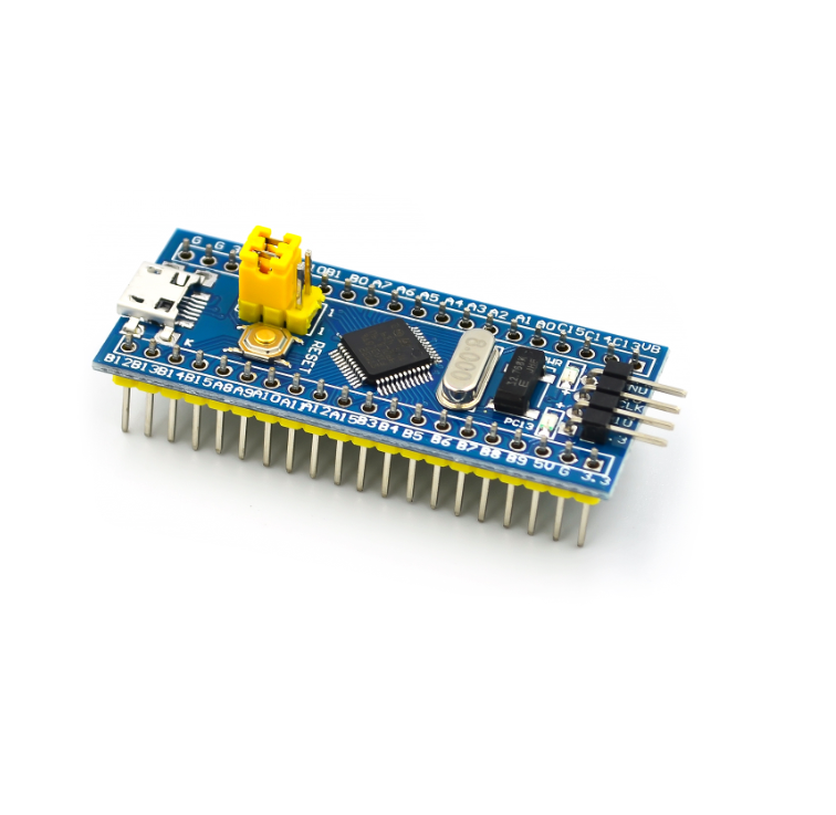
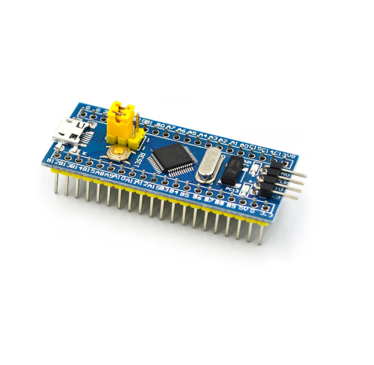
This is a core chip based on the STM32F103C8T6ARM core board. Its functions are as follows:
1. The motherboard is based on the most basic MCU circuit, 8M and 32768 crystal oscillator circuit, USB power supply circuit.
2. The core board is divided into two lines, leading to all I / O ports.
3. With SWD simulation debugging download interface, simple and convenient, and fast debugging speed.
4. Use Mirco USB interface, can do USB communication and power supply, USB interface, compatible with ordinary Android mobile phone charger interface.
6. The RTC Crystal Epson brand is easy to start and more stable.
7. With double needles, but the pins are not welded by default. Users can choose the welding direction that suits them according to their application scenarios.
Chip description:
Packing type: LQFP
Number of pins: 48
Core: Cortex-M3
Working frequency: 72MHz
Storage resources: 64K Byte Flash, 20KByte SRAM
Interface resources: 2x SPI, 3x USART, 2x I2C, 1x CAN, 37x I / O port
Analog-to-digital conversion: 2x ADC (12 bits / 16 channels)
Timer: 3 general-purpose timers and 1 advanced timer
Debug download: Support JTAG / SWD debug interface download, support IAP
RT9193: 3.3V voltage regulator chip, the maximum output is 300mA
Interface Description:
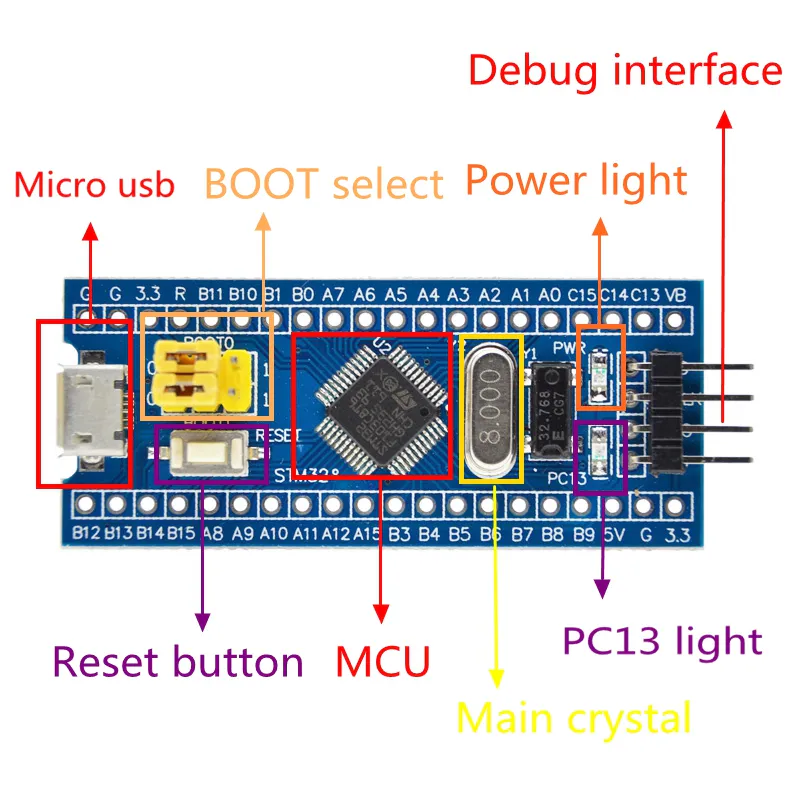
1. SWD interface: support simulation, download and debugging.
2. Mirco USB interface: power and USB communication, does not support download.
3. USART1 interface: USART1 can be used to download programs, or use USART1 for communication.
4. MCU pin interface: Lead out all I / O port pins to facilitate connection with peripherals.
5. 5V and 3.3V power input and output interface: commonly used for external power supply, or grounded with other modules
Description of other equipment:
1. Power indicator light (PWR): The status of the power indicator light can determine whether the power supply is stable.
2. User LED (PC13): Convenient for I / O output test or instruction program operation.
3. Start jumping to select the programming mode: (1, user flash memory 2, SRAM 3, system memory).
4. Reset button: reset the chip for the user program.
5. 8M crystal oscillator: The frequency can be set so that the system main frequency is 72MHz.
6. 32.768KHz crystal oscillator: can be used for built-in RTC or calibration.